Monday, September 29, 2014

CREATING 0805 SMD DESIGN IN SOLIDWORKS #24

Here's the previous part of the tutorial "http://shortedwire.blogspot.com/2014/09/creating-0805-smd-design-in-solidworks.html"
Now click on the features and extrude Boss /Base. Then enter the value 0.5mm.


Then the result likes


Now create a new part file and do same with dimensions 1.25mm x 0.35mm.


Save the file with "side" name.

Again create a new file and click on assembly this time.


Now click on insert component.


Now click and drag the component drag the side twice and body once and screen will be like.


Now click on the highlighted two faces and click on mates. 


Then the two faces will be collinear and like.


Similarly do same for all the faces which needs to collinear and finally results the 0805 package.


Finally save it as STEP 14 file and then import it to altium. 


Thursday, September 25, 2014

CREATING 0805 SMD DESIGN IN SOLIDWORKS #23

First start solid work click new and click new part.

Now hit OK.


Now click on SKETCH on top left corner.


Then click on front plane then sketch will start.


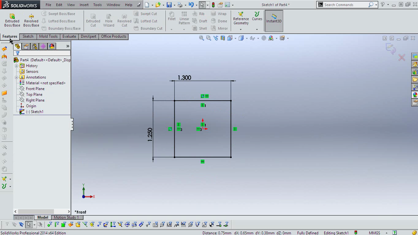
Click on rectangle tool. 


Then drag a rectangle


Now click on Smart Dimension from the toolbar. 


Click and drag the dimension from the rectangle


Enter Dimension 1.3 mm and hit enter


Do same for the other side but with 1.25mm dimension.
Then right click on the line as shown in the image below.


Then click on the select midpoint and holding down the control click on the origin. 


Then click on vertical. This will turn the vertical lines to black.(This is not cumpulsory step.)


Now do same for the vertical lines also and hit horizontal option and this will turn all rectangle to black color.


Now the rectangle is all done and i'll continue on the next post. 

Here' you get in end. 


Then at the very end and will be using it with Altium Designer 14


Wednesday, September 24, 2014

A SIMPLE DUAL POWER SUPPLY CIRCUIT #22

Dual power supplies are required mainly in signal purposes mainly in opamps and in amplifiers.
Amplifiers need high current supply and high voltages for delivering very high watt power to the speaker.
A very simple dual power supply can be make just using capacitor and resistor divider.


Here connecting B+ voltage will give output of +B/2 and - B/2 with respect to PGND on the terminal.
This circuit is used in SINGLE POWER SUPPLY CLASS D AMPLIFER of International Rectifiers' IR4301 and works real good.Here's the link of the IR's amplfier's circuit.
http://www.irf.com/technical-info/refdesigns/iraudamp17.pdf
Besides classical transformer based dual power supply will always works nice and fine.


Monday, September 22, 2014

CHEAPO ETHERNET FOR YOUR CONTROLLER #21

Enc28J60 is Microchips' cheap 28 pin 10BASE-T stand alone ethernet controller IC with both MAC and PHY. IC's available in DIP,SOIC,SSOP,QFN packages and quite popular in embedded designs.
Its interfaced to controller with SPI interface and has got 8K of Buffer RAM. Many breakouts are availabe for the board but why not build one of you own.
Things we need

J006d21BNL is RJ45 connector with internal transformers. These are available in digikey or any other supplier.
ENC28J60-I/SP is DIP package http://www.digikey.com/product-detail/en/ENC28J60-I%2FSP/ENC28J60-I%2FSP-ND/1680061

The whole schematics looks
The symbol here in C3 and in BOM above is mistaken for L3. The schematic for the capacitor should be inductor for value around 10 to 47 uH.

Here's a single layered home made PCB for the schematic.
With some nice 0805 100nF capacitor decouplings and SMD regulator below the board.
OOPs no 3d for connector..


Sunday, September 21, 2014

YOUR OWN USBasp PROGRAMMER #20

USBasp Programmer are used to program AVR microcontrollers. These programmers are used as ICSP (In Circuit Serial Programming). 
AVR's ISP header are generally in 10 pin format or in 6 pin format as in arduino.


The ISP pins are connected to the AVR's SPI pins and programming can only be done if SPI downloading is enabled and external reset pin is not disabled. 

USBasp can be used with some softwares like EXTREME AVR PROGMMER and even ARDUINO.
AVR dude also supports USBasp uploading.
USBasp firmware is readily available and it uses ATMEGA8 and used AVR's VUSB for making firmware only USB driver.


The PCB is like with USB B connector.


And some 0805 100nF decouplings below.
The usbasp firmware and circuit with drivers for PC are available from its site http://www.fischl.de/usbasp/

Thursday, September 18, 2014

THIS IS HOW CAMERA FLASH WORKS #19

In cameras, they have small battery with 3 volts of AA sized battery or with 3.7 volts of the Lithium Ion battery. But even with these very small voltage it gives very big flash. How this can be possible.
The flash we see comes from a flash tube filled with xenon gas.

These tube works with extremely high voltage, the xenon flash tube works with about 300 volts and to trigger the flash it requires about 2000 volts. But from small voltage it requires some circuit for generating very high voltage and the voltage is stored in a big capacitor generally >300 volts and about 150uF to 300uF.

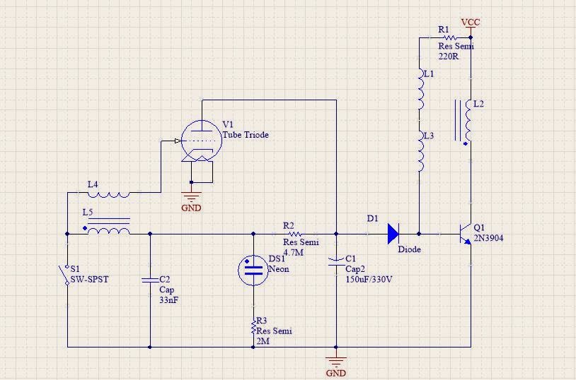
Here Vcc is is 1.5 v or 3v. The first transformer is formed by  L1,L2 and L3. This transformer has very high turn ratio and give output about 400 volts on the high side of transformer ie in L1 and L3 side. First from the base current flows and turns ON the transistor Q1 and current flows from L2 due to the flux generated with inturn create opposite flux and induces opposite voltage in the L1 side only a small amount of voltage is fed to base. The induced opposite voltage goes to very low to -400 volts and diode D1 no rectifies it and clipps off the positive voltage and acts like peak detector and charges capacitor to C1 to voltage bout 330 volts .
The oscillation frequency is about 10 Khz thats why we here some small sharp humming noise when flash is charging in camera.
When Capacitor c1 charges to full voltage Neon bulb lits up indicating flash is charged. Small capacitor c2 also charges to 330 volts and then when shutter button is pressed ie s1 is closed the voltage in c2 discharges very quickly which give a very small pulse in primary coil L5 and while secondary in L4 has very high number of turns and generate about 2kV for small time. This voltage is given to gate or trigger of xenon tube which turns on the tube and all the voltage of c1 is discharged and give a very high intensity of white light, which we call it flash.

Wednesday, September 17, 2014

MULTI THREADING IN ARDUINO #18

Multi Threading makes the operation of multiple threads or process to run at a same time.What is does is switches between two tasks very quick so that it seems all the jobs are done at same time . This is pseudo parallelism. First we need a standard C PT thread library.
Here's the link for the PT library.
https://drive.google.com/file/d/0Bx0yz8JxaXcALWQ4WUVJaFl2c3M/edit?usp=sharing

Second we need to extract the library and then add the folder to arduino library folder.
Then include the file in our code using

#inlcude  <pt.h>

Now lets blink two leds attach to pin 13 (default led pin) and add another to pin 12.Toggle them with  500 ms and 1000ms with these line of codes.

static int LED_1 = 13;
static int LED_2 = 12;
static long led1rate = 500;
static long led2rate = 1000;

Now we have two tasks to do, one to toggle led 1 and another to toggle led 2. And lets make a function with toggles andy gpio pin.

static struct pt pt1,pt2; // This makes two threads to create called pt1 and pt2.

void led_toggle(int led){
  digitalWrite(led,!digitalRead(led));//toggles the pin led.
}

Now defining the duration of the threads to call using

pt *pt is pointer to out thread variable
led is pin number and timeout is delay for toggle.

static int thread1(struct pt *pt,int led,long timeout){
  static long t1=0;//static timer which sets only once
  PT_BEGIN(pt);//thread begins here
  while(1){
    PT_WAIT_UNTIL(pt,(millis()-t1)>timeout);//wait until time out period here and do another task
    led_toggle(LED_1);//toggle led
    t1=millis();//get current time
  }
  PT_END(pt);//threads end
}

and in the case for the led two

static int thread2(struct pt *pt,int led,long timeout){
  static long t2=0;
  PT_BEGIN(pt);
  while(1){
    PT_WAIT_UNTIL(pt,(millis()-t2)>timeout);
    led_toggle(LED_2);
    t2=millis();
  }
  PT_END(pt);
}

Now lets setup the project using void setup
void setup() {
  pinMode(LED_1,OUTPUT);
  pinMode(LED_2,OUTPUT);
  PT_INIT(&pt1);// initialize the threads
  PT_INIT(&pt2);
}


Now run the loop forever. then the led starts blinking with led1rate and led2rate foreever.
void loop() {
  thread1(&pt1,LED_1,led1rate);
  thread2(&pt2,LED_2,led2rate);
}

Here's the all code in once. .

#include <pt.h>
static int LED_1 = 13;
static int LED_2 = 12;
static long led1rate = 500;
static long led2rate = 1000;
static struct pt pt1,pt2;

void led_toggle(int led){
  digitalWrite(led,!digitalRead(led));
}

static int thread1(struct pt *pt,int led,long timeout){
  static long t1=0;
  PT_BEGIN(pt);
  while(1){
    PT_WAIT_UNTIL(pt,(millis()-t1)>timeout);
    led_toggle(LED_1);
    t1=millis();
  }
  PT_END(pt);
}

static int thread2(struct pt *pt,int led,long timeout){
  static long t2=0;
  PT_BEGIN(pt);
  while(1){
    PT_WAIT_UNTIL(pt,(millis()-t2)>timeout);
    led_toggle(LED_2);
    t2=millis();
  }
  PT_END(pt);
}

void setup() {
  // put your setup code here, to run once:
  pinMode(13,OUTPUT);
  pinMode(12,OUTPUT);
  PT_INIT(&pt1);
  PT_INIT(&pt2);
}

void loop() {
  // put your main code here, to run repeatedly:
  thread1(&pt1,LED_1,led1rate);
  thread2(&pt2,LED_2,led2rate);
}

Thursday, September 11, 2014

SELECTING YOUR VOLTAGE REFERENCE FOR ARDUINO #17

Arduino’s getting very much popular for DIYers due to its extremely easy interfacing and coding environment.


World’s is analog. That’s why analog to digital conversion is most for the Microcontrollers to get interfaced with outer world. Most of the raw sensor will give analog voltage or current as output.Like LM35 temp sensor. While other digital sensor’s got there own processors inside to give output in some standard format like SPI, IIC, Serial , or like 232 level or 485 or SDI level  of signals.
Using ADC’s need analog reference for operation . This is the voltage to which the Adc compare in analog input voltage and gives equivalent output digital value.
ADC’s measured with bit like 8 bits, 10 bits , 22 bits and something like that.
For a Adc with 5 v as reference with 10 bits output. What it does is it divides  5v by 2^10.
Which means ADC and detect the change in input voltage or signal by 5/2^10. This means about 5 mV.
But in actual its Vref / (2^(n ) -1).
Now,Vref, in many micontroller are generated internally by internal band gap reference , while it can be switched to external pin or to VDD.
Now what we’ve got is Vref should be chosen according to sensor’s output resolution. The less the Vref the more the sensitive is out ADC but also the input to ADC can never be higher than Vref. So with larger Vref resolution get decreased so higher ADC should be used.
In arduino Aref is by default the supply voltage.
It can be changed to INTERNAL reference. Internal reference on ATMEGA 328 and 168 is 1.1 v while in ATMEGA 8 is 2.56 volts. These got 10 bit of SAR ADCs with 6 channels.
Then it can be switched to external pin Aref.
This can be changed with line
analogReference(type);
where type is DEFAULT(5V OR 3.3V),INTERNAL(1,1V ON 168 AND 328 OR 2.56V ON MEGA8), INTERNAL1V1(1.1V ON MEGA328),INTERNAL2V56(2.56 ON MEGA328),EXTERNAL(AREF PIN).
Arduino Due got 32 bit ARM processor and got some more channel’s on ADC. Its running on 3.3 .
In Due analogReadResolution(1 to 32); can change the output resolution it got 12 bit of ADC with output ranging form 0 to 4095. Using parameter >12 make the 0 padding in extra bits.
Here’s the DUE’s analog read resolution page by arduino.

Here’s a quick comparision on ADC and other parameter on arduino boards http://www.djerickson.com/arduino/

Wednesday, September 10, 2014

HALL SENSOR USING SS49E #16

Hall sensors basically senses the magnetic field. What's Hall voltage is when magnetic field is passed perpendicular to the conductor carring a current in certain direction will produce a voltage accross its body. What google says is
  1. The Hall effect is the production of a voltage difference (the Hall voltage) across an electrical conductor, transverse to an electric current in the conductor and a magnetic field perpendicular to the current. It was discovered by Edwin Hall in 1879.
Now what hall sensor does is when magnetic field is detected hall voltage is generated within the sensor and voltage is given as output.
Hall sensors are available as digital , analog and some very complex progarmmable.
For example SS49E by honeywell is cheap analog sensor.
TLE4997 by Infineon is programmable hall sensor.
MLX90242 of Melexis is a Hall switch.
Besides there are many other types. You can check it out in digikey list http://www.digikey.com/product-search/en/sensors-transducers/magnetic-sensors-hall-effect-digital-switch-linear-compass-ics/1967232?k=hall%20sensor

Hall sensors are availabel mostly in SOT23 packages and SIP packages, besides there are other packages but not used mostly.
One of the common use of Hall sensor in RPM measurement in CPU fan.

The LD1117 ,here, is SOT223 package adjustable voltage regulator. SS49E is 5V device but it can be used for lower voltage. 
The no field output voltage is VCC/2. When field is detected according to polarity of the field its voltage will rise or fall. 
The sensitivity is 1.2mG/mV.
The sensor can be used for the sensing current. According to direction of the current the output voltage will rise or fall.
The PCB is some what like


Saturday, September 6, 2014

16M color using RGB led and arduino #15

RGB leds have 4 leads in it. RGB leds ase like common led but its just three led with RED GREEN and BLUE colored LED in single LED body . Each pin are for red , green and blue colored led and one for ground.
Using Arduino's PWM feature we can change the intensity of each of the individual led and the color of the led will give the 2^8 level ie 255 for each color. Then with three eight bit colored led it will give 2^24 level of color. I.E about 16 million of color.But our human eye couldn't detect all those colors.
Now connect the pins of RGB led to any of the PINS in arduino labeled with PWM or ~ kind of symbol.


Most of the RGB led have the above pin configuration. The cathode pin is ground connected to arduinol's ground and other to any of the PWM pins lets say 9 to R,10 to G and 11 to B.
In arduino's program add
#define R 9
#define G 10
#define B 11

In setup() add
pinMode(9,OUTPUT);
pinMode(10,OUTPUT);
pinMode(11,OUTPUT);

Now any where in program we can adjust the brightness of each of the led to change the color the led using analogWrite(X,VALUE);
where X is either R, G or B
and VALUE is anywhere between 0 to 255. Its always better to and some resistors 220 to 330 (around)  to the R G and B pins in series to arudino 's pin to limit the current flowing.


Thursday, September 4, 2014

CHEAP STANDALONE ARDUINO #14

This tutorial shows how to use arduino or atmega 328 IC with very least external peripheral or no peripheral at all. You just need to supply the 5 volts to it and its running the program in it.
First components required are
a) ATMEGA 328P
b) AVR programmer (any may be arduino as isp )

First plug the ATMEGA on breadboard.


Connect the MOSI,MISO,CLK and RESET pin of the ISP to the MOSI(17),MISO(18),CLK(19) and RST(1) of the chip on board.  And supply the voltage to pins 7 8 and 22.
I am using MEGA as ISP so CLK(52) goes to 19 pin, MOSI (50) goes to MISO(18) , MISO(51) goes to MOSI(17) and RST (53) goes to RST(1) of the chip on board .

After go to C:\arduinoxxxx\hardware\arduino\avr\boards.txt 
and open it using some editing software like notepad, wordpad or notepad++ then append these lines at the end
##############################################################

atmega328bb.name=ATmega328 on a breadboard (8 MHz internal clock)

atmega328bb.upload.protocol=arduino
atmega328bb.upload.maximum_size=30720
atmega328bb.upload.speed=19200
atmega328bb.upload.tool=avrdude

atmega328bb.bootloader.tool=avrdude
atmega328bb.bootloader.low_fuses=0xE2
atmega328bb.bootloader.high_fuses=0xDA
atmega328bb.bootloader.extended_fuses=0x05
atmega328bb.bootloader.file=atmega/ATmegaBOOT_168_atmega328_pro_8MHz.hex
atmega328bb.bootloader.unlock_bits=0x3F
atmega328bb.bootloader.lock_bits=0x0F

atmega328bb.build.mcu=atmega328p
atmega328bb.build.f_cpu=8000000L
atmega328bb.build.core=arduino
atmega328bb.build.variant=standard


Now plug in the avr isp programmer and open arduino environment. Now a new line will be available 


Choose the ATmega328 on breadboard(8Mhz internal clock). 
Now again browse to "C:\arduino-xxx\hardware\arduino\avr\bootloaders\atmega"
Open the folder and paste this hex file in it.https://drive.google.com/file/d/0Bx0yz8JxaXcAU3pra0o5eTZMY1k/edit?usp=sharing

Now plugging the isp burner and choose the correct programmer in programmer menu.
Then hit burn bootloader. This may take a while and can see the conformation message "bootloader upload successful" in the arduino screen. 
Then we are done. Now just give your controller the juice it need and its ready to go. Its running on 8MHz internal crystal and also no reset pull up is required.Its better to give decoupling in power in better practice.