For testing the antenna, we
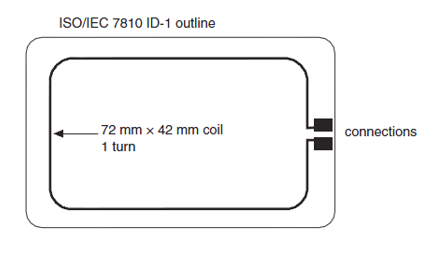
first made a loop antenna as per reference to ISO/IEC 7810 ID-1 outline as per
the figure shown below with dimension given.
o Then an experimental setup was made as shown
below:

o The signal generator is connected across the
antenna we had designed and then this PCB antenna board was placed on the loop
antenna, which was connected to oscilloscope to view the frequency, and the
voltage induced in the loop antenna (with 50Ω input resistance).
o While measuring the inductance of the antenna
alone using LCR meter, we observed it to be 3.6 micro henry at 1mhz. Since our
LCR meter can only measure up to 1uH, we used hit and trial method using
convergence of the resonant frequency by calculating the tuning capacitor and
inductor each time with the frequency that was seen on oscilloscope.
o The initial tests and results made showed the
result as:
Antenna +
30pf(NFC ic equivalent) capacitor in parallel
|
At 26mhz, induced voltage = 150mv
|
At 15.8mV, induced voltage = 50mv
|
At 43.8mhz, induced voltage = 80mv
|
Antenna + 30pf(NFC ic equivalent) +10pf(tuning
capacitor) in parallel
|
At 27.6mhz, induced voltage = 474mv
|
o From the above, result we figured out that the tuning of capacitance leads to increase in the induced voltage as well resulting the increased efficiency. But the problem was the antenna was still tuned to 27.6Mhz, that is around next order of our required frequency 13.56mhz. i.e double than the required.

o In above picture, we can see the voltage induced
in loop antenna from our designed antenna when initially only some random
tuning capacitor of 40pf was placed and the frequency was not tuned yet.
o So to tune the antenna to the 13.56mhz, we first
calculated the inductance at the frequency at which the highest voltage was
induced and by placing value of capacitance as the used capacitor value. For
this

formula was used.
formula was used.
o For initial tuned frequency = 27.6mHz, tuning
capacitor = 40pf, resultant calculated inductance was 0.83131uH.
o So, in next iteration we used frequency =
13.56mhz, inductance = 0.831831uH, the calculated capacitor was 165.71pf.
o So, next time we put this capacitor in the
circuit. In continuing this iteration for several run, we got the calculated
capacitor as 400pf and actual used capacitor as 380pf to get the resonant
frequency at 13.56mhz and the maximum voltage induced.
o Below is the maximum induced voltage at our
required 13.56 mhz signal. But the efficiency is still low so which seems to be
enough to get signal but not power up the circuit. (further study should be
done on knowing about if this induced signal is enough or not as well as
increase the efficiency)

Induced signal on loop antenna input signal (13.56mhz @ 5V
p-p)
o We also checked our designed antenna as receiver
and the previously available 13.56mhz signal generator. The setup and response
is shown in figure below.

o Here we can see almost 3V was induced in our
designed antenna.
We
need to further study about antenna design, antenna tuning and antenna testing
(use of network analyzer, use of antenna design software etc) and implement in
our next version board.