Friday, November 28, 2014

CHOOSING AND DRIVING A MOSFET #1 #28

MOSFETS are some what confusing than the Bipolar Juntion Transistors BJT or simply transistors. MOSFETS (Metal Oxide Semiconductor Field Effect Transistors) are voltage controlled current source (VCCS) while BJT are current controlled current source. One of the well known relation for the transistor is Ic = B Ib. Where  B is beta or Hfe current gain of the transistor and is usually >10 for high power transistors and >100 for small signal transistors. 
So controlling the current flowing in the Base of the transistor one can control the output current flowing from the collector to emitter or from emiter  to collector in case of NPN and PNP transistors. 
High power transistors require more silicon space in comapre to the same space with the MOSFETS.


In case of Mosfets, they are of N channel and of P channel. Both have its own advantages and dis advantages. But the common of the Mosfets are that both the Mosfets only start conduction when the voltage in its GATE terminal exceeds some voltage level than that of the voltage level in source, which is called Vgs = Vth = Gate threshold voltage. Understanding this voltage level is very important for the design withe Mosfets. Vgs voltage from gate to source is position in the case of the N channel but for the P channel its in negative. But it is still easy to drive the gate of the Mosfets.


N channel have some advantages as they have electrons as their carrier and they have more mobility so the N channel mosfets have very low ON resistance called Rds than the P channel mosfet with same size of die or silicon and this reason need of more silicon space also make P channel mosfet more expensive. 

Wednesday, November 5, 2014

SVN VERSION CONTROL IN ALTIUM #27

Version control in makes any project very easy to manage and work with different versions of the same projects and makes modifications and make easy management of all the versions and storing of all the versions.
In Altium, it has got its own version control and also SVN external version control.

THIS TUTORIAL IS ONLY FOR THE VERSION CONTROL OF THE PROJECTS IN LOCAL COMPUTER ONLY.

Step 1: Make new PCB project.


Step 2: Then go to preferences of ALTIUM  and navigate to Data Management and Version Control
and check the User external Suberversion Radio button and check on SVN-Suberversion check box. Or click on Auto Detect.


Step 3: Now click on Design Repositories and click on Create New and Click on SVN.


Step 4: Name Repository some name like "MyRepo" and in location choose the folder where you work. Mine is "altiumrepo". Then Hit OK.
The status will be green if everythings OK.


Step 5: Now on project right click and choose version control and add project to version control.


Step 6: Choose the Repo and Hit OK.


Now we can comit the project or inidivual file from the same menu by right clicking it . For check out go to storage manager and right click and click on revert on specified file or project.


Monday, October 27, 2014

FTDI Bricking all the non genuine FTDI chips #26


FTDI are used for easy USB connections in microcontroller and are widely used.  FTDI updating drivers in windows machine for detecting the counterfeit Ics and then re writing their internal eeprom’s Product id to zero so that no machine can read the usb device again. They are bricking the chips and no use for  further.
FTDI been hitting their own market and all the users are real mad. Here’s the video on EEVLOG. https://www.youtube.com/watch?v=eU66as4Bbds


Friday, October 10, 2014

ENABLE LARGE CROSS HAIR IN ALTIUM DESIGNER #25

We have the default small cursor as

Then to change to large cursor or cross hair.


Step 1 :
Go to preferences. DXP -> Preferences or Tools -> Preferences


Step 2:
Navigate to PCB editor -> General.


Step 3:
Click on the drop down menu with small 90 chosen.


Step 4:
Choose large 90 and hit enter or OK.

Then its done.

Monday, September 29, 2014

CREATING 0805 SMD DESIGN IN SOLIDWORKS #24

Here's the previous part of the tutorial "http://shortedwire.blogspot.com/2014/09/creating-0805-smd-design-in-solidworks.html"
Now click on the features and extrude Boss /Base. Then enter the value 0.5mm.


Then the result likes


Now create a new part file and do same with dimensions 1.25mm x 0.35mm.


Save the file with "side" name.

Again create a new file and click on assembly this time.


Now click on insert component.


Now click and drag the component drag the side twice and body once and screen will be like.


Now click on the highlighted two faces and click on mates. 


Then the two faces will be collinear and like.


Similarly do same for all the faces which needs to collinear and finally results the 0805 package.


Finally save it as STEP 14 file and then import it to altium. 


Thursday, September 25, 2014

CREATING 0805 SMD DESIGN IN SOLIDWORKS #23

First start solid work click new and click new part.

Now hit OK.


Now click on SKETCH on top left corner.


Then click on front plane then sketch will start.


Click on rectangle tool. 


Then drag a rectangle


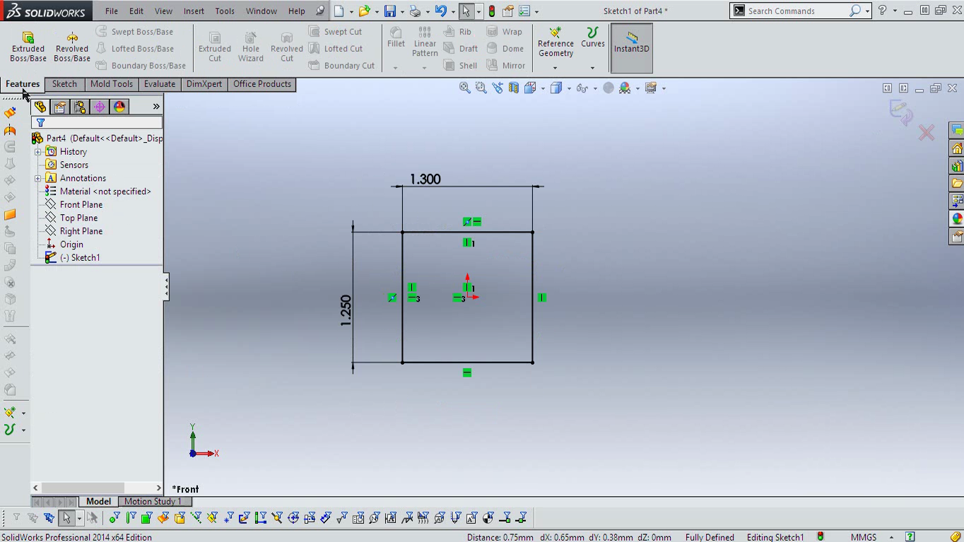
Now click on Smart Dimension from the toolbar. 


Click and drag the dimension from the rectangle


Enter Dimension 1.3 mm and hit enter


Do same for the other side but with 1.25mm dimension.
Then right click on the line as shown in the image below.


Then click on the select midpoint and holding down the control click on the origin. 


Then click on vertical. This will turn the vertical lines to black.(This is not cumpulsory step.)


Now do same for the vertical lines also and hit horizontal option and this will turn all rectangle to black color.


Now the rectangle is all done and i'll continue on the next post. 

Here' you get in end. 


Then at the very end and will be using it with Altium Designer 14


Wednesday, September 24, 2014

A SIMPLE DUAL POWER SUPPLY CIRCUIT #22

Dual power supplies are required mainly in signal purposes mainly in opamps and in amplifiers.
Amplifiers need high current supply and high voltages for delivering very high watt power to the speaker.
A very simple dual power supply can be make just using capacitor and resistor divider.


Here connecting B+ voltage will give output of +B/2 and - B/2 with respect to PGND on the terminal.
This circuit is used in SINGLE POWER SUPPLY CLASS D AMPLIFER of International Rectifiers' IR4301 and works real good.Here's the link of the IR's amplfier's circuit.
http://www.irf.com/technical-info/refdesigns/iraudamp17.pdf
Besides classical transformer based dual power supply will always works nice and fine.